Overview
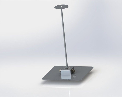
The Active Monopole Antenna VAMP 9243 consists of a vertical rod and an impedance matching amplifier. The rod has a standard length of 1m (other rod length on request) and can be considered as short compared to the wave length in the frequency range 9 kHz-30 MHz.
The conversion factor is independent of the frequency because of the extremely high impedance of the matching amplifier. The circuit gives best results of noise and intermodulation for a conversion factor (antenna factor) of +10 dB and sensitive measuring receivers are able to use the whole dynamic range of the antenna.
For very high fieldstrength, an optional plug-in attenuator reduces the amplification by 20 db. In order to avoid absolutely any influence by the mains, power supply, voltage regulator a. o., the VAMP 9243 has built-in NiMH rechargeable batteries. The typical operation time is at least 50 hours.
Charging time is 2-4 hours using the quick charger. Rod antenna and amplifier cabinet are made of aluminium. The top plate can be fixed to the metal ground plane (Counterpoise) with 4 screws. The connectors and controls are situated below the top plate. The rod length begins exactly at the top plate.
| Technical Data | |
| Frequency range | 9 kHz - 30 MHz |
| Conversion factor ("Antenna factor") | +10 dB/m+-1.5 dB |
| Upper limit of field strength measurement | 1 V/m (F=1 MHz, 1 dB compression) Input attenuator for higher field strength optional |
| Lower limit of field strength measurement | Limitation by internal noise. Typ. - 3 dBµV/m / 10 MHz CISPR-Quasipeak 9 kHz bandwidth Typ. -8 dBµV/m / 10 MHz Average detector 9 kHz bandwidth More information is given in the diagrams further down this manual. |
| Output of the monopole amplifier | BNC-connector, fem., 50 ? nom. |
| Power supply | 9,6 V /1100 mAh NiMH |
| Dimensions and weight | Monopole (Rod): Length including thread connection 1m Weight approx. 0,2 kg |
| Amplifier | 180x80x40 mm (WxHxD) without BNC-connector (female) and controls. Top plate 220x120 mm Weight approx. 0,7 kg |
| Construction of the monopole (Rod) | Aluminium rod 16 mm diameter with thread-hole M8 |
| Construction of the amplifier | Cabinet made of aluminium profiles. Top plate 3 mm aluminium material. |
| Threads for tripods | 1/4", 3/8" |
Switching On
Put ON/OFF switch into ON-position. The green LED has to be on.
Combinations of green and red LED:
Green: Battery OK
Green + red: Battery reserve
Red: Low battery
The antenna will operate even with low battery, but with restricted performance.
Application
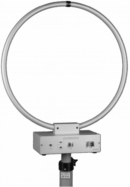
Basically the active monopole antenna is an electric field strength adapter. In combination with our magnetic field probes, for example FMZB 1537, electric and magnetic field strength can be measured separately with high sensitivity in the frequency range from 9 kHz - 30 MHz. Standards, especially in the automotive field, give very precise specification for the measuring site. Usually the monopole antenna is mounted on a metal (electric) counterpoise. Measurement is made in a shielding room.
Integration
The VAMP 9243 is intended for indoor operation in shielded rooms. Supervised outside operation under dry weather conditions is also possible. For this reason threads for tripod mounting and rubber feet are provided. A permanent use outside is not permitted.
Do not mount the rod before the installation of the amplifier box to the counterpoise is completed. Fix the bottom plate of the amplifier with screws to the (electric) counterpoise. Both plates must be in good electric contact.
The coaxial cable is running under the counterpoise in order to avoid coupling or field deformation. The coaxial cable is on one end connected to the bnc-connector of the VAMP 9243 and on the other end to the input of the measuring receiver.
In order to provide best sensitivity, the VAMP 9243 does not use special protection circuitry on its rod input.
Therefore use the antenna with caution and care.
Discharge the rod to the counterpoise before connecting it to the amplifier.
Fix the rod by srewing the bottom M 8 thread to the stud on top of the amplifier cabinet.
A good receiver will now show a significant increase of noise if set to high sensitivity, when the antenna is positioned in a shielded room.
Outside of a shielded room internal noise will be completely covered by interference signals.
The monopole antenna is now ready for measurement. Remove the rod after measurement. This is very important, if nearby immunity testing with high power generators will be done.
Before removing the rod discharge the body capacity by touching the counterpoise.
Measurement
The probe converts electrical fieldstrength into a voltage (across 50 ?), which is indicated by a measuring receiver, spectrum analyser or r.-f.-millivolt meter. The fieldstrength can be calculated using the antenna factor (conversion factor, transducer factor) of the probe. This factor is +10 dB/m and is practically constant in the specified frequency range.
Preferably a measuring receiver with a 50-?-input and dBµV-reading will be in use. Reading in dBµV is very common in the emc-field and available on almost every receiver, using 0 dBµV acc. to 1 µV.
The voltage level on a certain frequency (f. e. an am transmitter on 1 MHz) is measured. The antenna factor of +10 dB (typ.) is added to the voltage level reading. The result is the electric fieldstrength level in dBµV/m
| Example 1 | |
| Voltage level reading on the receiver | 60 dBµV |
| plus antenna factor (typ.) | +10 dB |
| Electric fieldstrength level | 70 dBµV/m |
Receiver reading in dBm (0 dBm acc. to 1 mW). The power level is measured and 117 db added.
| Example 2 | |
| Power level reading on the receiver | -50 dBm |
| plus antenna factor (typ.) | 117 dB |
| Electric fieldstrength level | 67 dBµV/m |
Receiver voltage reading directly in V (mV, µV). The voltage is multiplied by 3,16 to get the electric fieldstrength in V/m.
| Example 3 | |
| Receiver reading (voltage) | 0,1 V |
| multiplied by antenna factor (typ.) | 3,16 Vx0,1 |
| Electric fieldstrength | 0,316 V/m |
Noise
The VAMP 9243 is optimised for lowest internal noise. Noise is the limit for the measurement of weak signals. Internal noise is common to all practical amplifiers, but the monopole amplifier is very much affected by this problem.
The reason is that there is deliberately no matching between rod and amplifier, because extremely high impedance is necessary to keep the antenna factor (conversion factor) independent of the frequency, which is very important for convenient measurement.
In the field of emi there are standardised detectors and bandwidths, which are related to frequency ranges.
Noise indication rises with bandwidth. Noise indication can be reduced by choosing smaller bandwidth. On the other hand it has to be considered that bandwidth must never be chosen smaller than the bandwidth of the signal to be measured. Otherwise the measurement will be too small.
There will be no problems measuring a clean sine wave signal (microprocessorcrystal oscillator), but modulated signals (a.m., f.m.) may have considerable bandwidth.
Even more bandwidth is consumed by electric motors, ignition systems and modern semiconductor circuits.
Therefore limits for pulse signals should always be measured with standard bandwidth (usually 9 kHz / -6 dB).
The same strategy is used to choose the detector. The lowest noise reading is obtained using the average detector, the highest reading comes from the peak detector. The CISPR-Quasipeak detector is in between.
Because of the fact that sine wave signals give the same reading with all three detectors, they can be measured with the low noise average detector. The limits for pulse spectrum are measured with Peak- or CISPR-Quasipeak according to the standards. Obviously these "tricks" are only important, if limits are very close to the noise floor.
The above considerations are only valid for the combination of the monopole antenna and a high quality, high sensitivity emi-receiver (Schwarzbeck FCKL 1528). A receiver which does not show a higher noise reading when connected to the VAMP 9243 cannot use the dynamic range.
Low quality, low sensitivity receivers or spectrum analysers without selective preamplifiers (preselectors with low distortion amplification) will completely determine the noise characteristics. Even the outstanding noise and amplification characteristics of the VAMP 9243 cannot improve this. The basic internal noise of the VAMP 9243 is so low that it can only be determined in perfectly shielded rooms. Otherwise parasitic signals will be misinterpreted as basic noise.
It is good practice to use the receiver's audio (loudspeaker) to detect the kind of signal.
If the sensitivity of a receiver or spectrum analyser is to poor to indicate the internal noise of the VAMP 9243, a sensitive preamplifier at the receiver's input will improve the situation, when low fieldstrength measurement is a must. It has to be mentioned that overload (intermodulation) problems with high fieldstrength may occur.
Large signal handling, Overload
Saturation and overload occurs with high input levels. One strong single sine wave signal or extended pulse spectrum can be the cause of overload. Virtually all combinations occur in everyday measurement. With only one single sine wave signal present on the receiver's input, a high reading shows very clearly that there may be an overload. This is more difficult with broad-band pulse spectrum, because most often there is no extremely high reading on a specific frequency. Overload can lead to both too high or too low reading. On one hand, compression of a sine wave signal will lead to a lower reading, on the other hand harmonics will be generated which lead to a higher reading on higher frequencies.
For high fieldstrength measurement we recommend the optional 20 dB plugin attenuator. It is inserted directly at the foot of the rod and reduces the voltage level in front of the amplifier's input. Because of the fact that the amplifier as the only active part is responsible for potential intermodulation, attenuation must be concentrated in front. Attenuation behind the amplifier will reduce amplification too, but without any improvement for large signal handling capability. Broad band circuits are generally more vulnerable to large signal handling problems. This is true for the rod amplifier as well as for the emi-receiver.
Low quality receivers or spectrumanalysers without preselectors may be overloaded by broad band spectrum.
Internal noise of the VAMP 9243
The internal noise was recorded with the emi-receiver FCKL 1528. The bandwidth is 200 Hz in the frequency range 9 kHz - 150 kHz and 9 kHz from 150 kHz - 30 MHz. This is the reason for the level difference at 150 kHz. The extremely low noise of the VAMP 9243 was amplified by 20 dB using the amplifier BBV 9740. The conversion factors are combined to -10 dB.
First discharge your body by touching the metal ground. Loosen the rod by turning it some turns ccw. Plug the ground pin of the attenuator into the ground connector near the rod. Turn the attenuator until the metal strap fits under the rod. Turn the rod cw. to fix the connection.
Conversion factor (Antenna factor)
The conversion factor of the VAMP 9243 without input attenuator is +10 dB/m. With plugged in attenuator it is +30 dB/m. Read the receiver measurement in dBµVm and add 30 dB/m to get the fieldstrength level in dBµV/m.


