CISPR 16-1-1
-
R&S ESW Series EMI Test Receiver
SKU: 11722
Frequency Range: 1 Hz up to 8, 26.5, or 44 GHzMeasurement Bandwidth: 1 Hz to 10 MHz (optional 80 MHz)Noise indication: < -5 dBµVCompliant per: CISPR 16-1-1, ANSI C63.2, MIL‑STD‑461 and FCC1 dB compression nominal @ 1 GHz: +15 dBmTypically In Stock -
Narda PMM 7010 EMI Test Receiver
SKU: 10025
Frequency Range: 9 kHz to 3 GHzApp Note: Differences Between EMI Test Receivers and Spectrum Analyzers, Precompliance conducted emissions,Detectors: Peak, Quasi-Peak, Average, RMS, RMS-Avg (optional), C-Avg, Smart Detector functionPre-programmed Test Limits: CISPR 11, CISPR 22Sweep/Test Speed: Slow$995.00IN STOCK -
Rent Keysight N9048B CISPR 16 EMI Receiver
SKU: 22153
Frequency Range: 1 Hz to 26.5 GHzStandards Met: CISPR 16-1-1, ANSI C63.2, FCCCalibration: Accredited ISO 17025Options: See "Installed Options"Applications: Conducted Emissions, Radiated Emissions,IN STOCK -
PMM ER9000 EMI Test Receiver
SKU: 12366
Frequency Range: 10 Hz - 3 GHzCompliant?: YesApplications: Conducted Emissions, Radiated EmissionsPre-programmed Test Limits: CISPR 11, CISPR 22, ANSI C63.2Other Features: Click Analyzer (CISPR 14-1)$2,500.00Typically In Stock -
Rohde & Schwarz ESW44 EMI Test Receiver for CISPR16-1-1, 1 Hz to 44 GHz
SKU: 6113
Frequency Range: 2 Hz to 44 GHzStandards Met: CISPR 16-1-1, ANSI C63.2, FCCCalibration: Accredited ISO 17025Options: B4, B21 or B8E, B21, B24Typically In Stock -
Keysight (Agilent) N9038A-526 MXE EMI Receiver, 3 Hz to 26.5 GHz
SKU: 10063
Frequency Range: 20 Hz - 26.5 GHzResolution: 2 HzBandwidth accuracy (–3.01 dB): 1 Hz to 1.3 MHz ± 2 % (nominal)Dynamic Range: > 70 dBAmplitude Accuracy: < ± 2.7 dBTypically In Stock -
PMM 9010
SKU: 11026
Frequency Range: 10 Hz - 30 MHzApplications: Conducted EmissionsTest Standards: CISPR 14, CISPR 16-1-1$4,700.00In Stock -
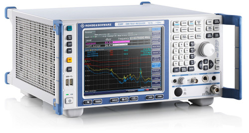
Rohde & Schwarz ESRP7 EMI Test Receiver per CISPR 16-1-1
SKU: 22721
Frequency Range: 9 kHz to 7 GHzSSB Phase Noise: –90 dBc (1 Hz) (typ.)Frequency Response: 100 kHz ≤ f ≤ 7 GHz, < 3 dBDynamic Range: 110 dBRF Output Connector: N Type Female, 50 ΩCALL FOR LEAD TIME -
3ctest TAN 8124 Artificial Network
SKU: 30134
Frequency Range: 0.1 - 110 (150) MHzMax. Continuous Current: 70 AMax. Current (Short Time): 100 AMax. Voltage (DC): 500 VMax. Voltage (AC 50/60 Hz): 250 VInquire for Lead Time


